Multilayer Printed Antennas and Arrays for 5G applications
The development of 5G communications has refocused antenna research in a variety of applicable frequency bands. World-wide deployment of 5G networks in the 3.5 GHz frequency band is currently very important for many countries, and motivated the present work. Antenna arrays have to be very directional and of sufficient bandwidth to support required wireless links. Further, they have to support dual polarization for Multiple-Input-Multiple Output (MIMO) protocols.
We describe a class of printed patch antennas that involve 3 metal layers all completely integrated within a single dielectric, which are of very high efficiency and significant directivity and gain. The printed antenna arrays developed are lightweight and monolithically integrated within a thin PCB and are excited through an intermediate dually-polarized coupler integrated within the PCB dielectric. The antennas presented exhibit high-purity dual linear polarization, very high efficiency, significant gain and sufficient bandwidth to be suited for sub-6 5G applications, producing advantageous antenna arrays that have thin profiles and are lightweight. The feeding mechanism through the intermediate dedicated coupler layer is designed to couple the input power to the antenna without a direct metal contact to the radiating patch, allowing single or dual polarization functionality. The corresponding arrays presented have significant beam-scanning capabilities of ±60°, which is important for establishing wireless links in corresponding deployments.
We have fabricated single-elements whose measured gains reach 7 dBi. We have also fabricated a 32-element array and have measured the performance of selected sub-arrays. A 4×1 oblong sub-array and a 2×2 square sub-array have been excited by an external 1-to-4 combiner and have measured gains in either orthogonal polarization reaching 13 dBi at the intended operation frequency. The entire 32-element rectangular array gains reach 21 dBi.
Theoretical simulations and measurements of fabricated prototypes are in very good agreement for both single-elements and arrays and validate the proposed designs.
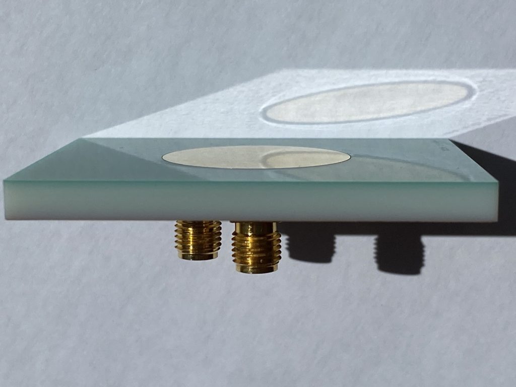
Fig. 1 shows a fabricated antenna element and the two feeds behind the PCB, each producing a linear polarization orthogonal to the other.
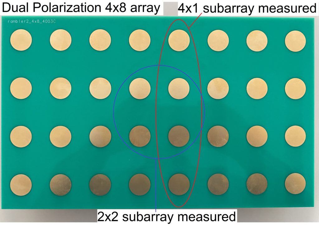
Fig. 2 shows a 32-element fabricated antenna array (front side) and the sub-arrays measured.
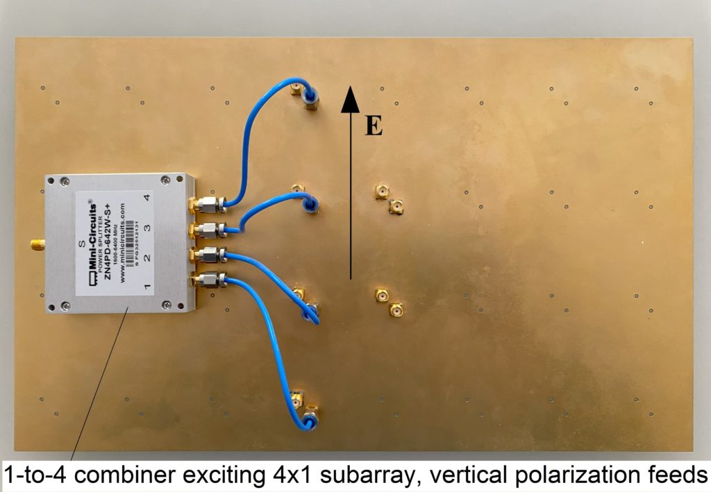
Fig. 3 shows the back side of the 32-element fabricated array and the excitation set-up of the vertically polarized measured 4x1 sub-array. The feeding is through an external 1-to-4 splitter/combiner that splits the main signal into 4 signals of equal magnitude and phase, preserving the excellent matching of the antennas. The direction of the radiated electric field is also shown.
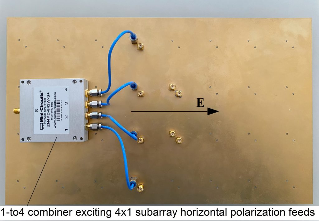
Fig. 4 shows the back side of the 32-element fabricated array and the excitation set-up of the horizontally polarized measured 4x1 sub-array through the same external splitter/combiner. The direction of the radiated electric field is also shown.
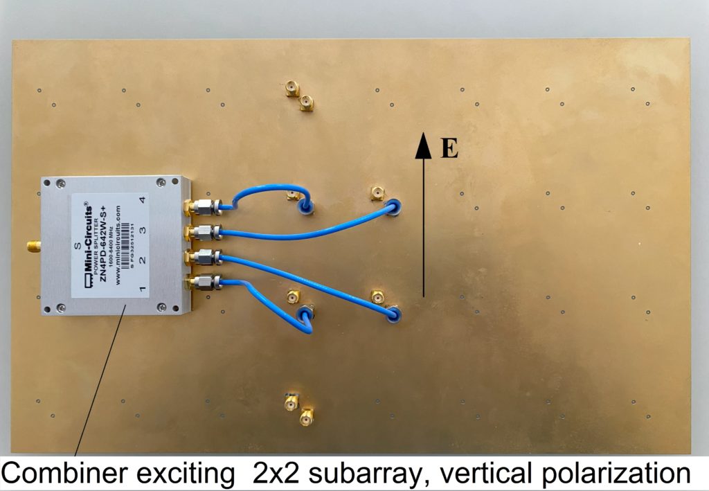
Fig. 5 shows the back side of the 32-element fabricated array and the excitation set-up of the horizontally polarized measured 2x2 central sub-array through the same external splitter/combiner. The direction of the radiated electric field is also shown.
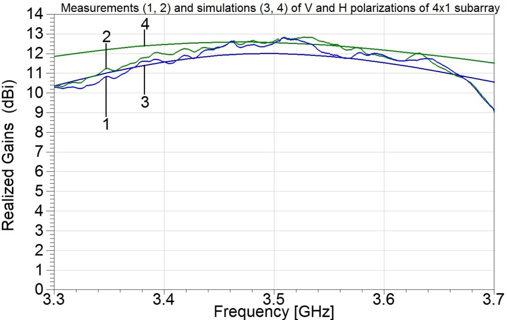
Fig. 6 shows the measured and simulated 4x1 sub-array gains of Figs. 3 and 4. Curves 1 and 2 are the measured gains for vertical and horizontal polarizations, while curves 3 and 4 are the corresponding theoretical simulations. The bandwidth of operation of the array (within the -10 dB impedance matching) is 250 MHz, centered around the center frequency of 3.5 GHz. Similar results hold for the 2x2 central sub-array measured.