Metamaterial Antennas and Arrays
Projected Curved Artificial Magnetic Conductors (PCAMC) integrated on printed antennas
e developed a new class of metamaterials that are planar low-profile artificial magnetic conductors (AMC) that act as curved magnetic mirrors, i.e., they project the AMC functionality on a curved surface, even though they are geometrically flat. We showed that these curved AMCs, despite their thin profile, focus electromagnetic waves similarly to curved metallic reflectors, and are ideal for new low-profile high-directivity antennas, integrable within standard packaging technologies. We focused our analysis on curved AMCs for the 60-GHz technology platform, but the approach is quite scalable in frequency. The unit cells are metallic spirals, but our approach holds for any other AMC unit cell design. As an application, two packaged 300μm -thick 60-GHz antenna systems have been designed occupying quite small areas. Prototypes have been fabricated and measured indicating excellent agreement with theoretical expectations, having gains of 9-10 dBi. Impedance bandwidths are 13–15 GHz, making this technology ideal for broadband, high-directivity 60 GHz radio applications.
We compare the electromagnetic properties of the flat AMC with the corresponding PCAMC under normal plane-wave incidence. In Fig. 1a we see a flat spiral AMC optimized to work at 60 GHz, where all AMC cells are identical. Fig. 1b shows the magnetic field vector distribution on the perpendicular mid-plane of the structure.
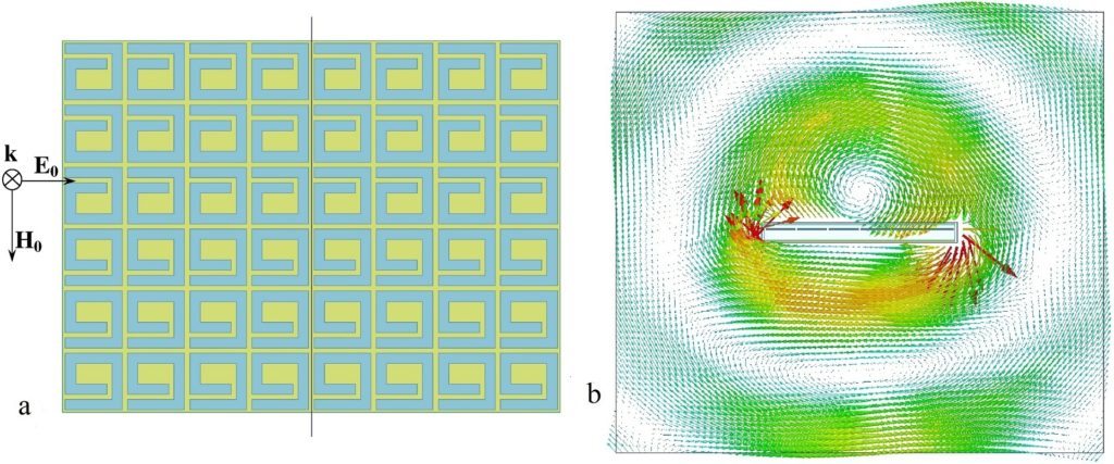
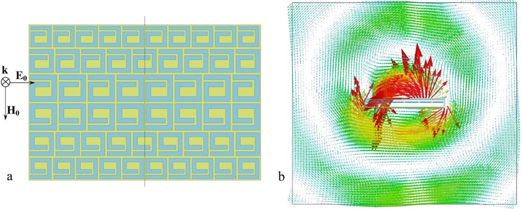
In Fig. 2a we show the PCAMC derived from the flat AMC design of Fig. 1a, by means of the general theory and algorithm developed in the present work. The spiral unit cells become smaller, as we move off-axis, and their horizontal density increases. In Fig. 2b we see the corresponding vector magnetic field distribution. The magnetic field is very strong and rotates around an effective focal line which lies on the surface of the PCAMC. This distribution is very similar to that of a real metallic half-cylindrical reflector having its true focal line at the same coordinates, except that the real cylindrical reflector would have a large radius, compared to the very small thickness of the PCAMC. Hence, the effective curvature of the structure of Fig. 2a has been demonstrated.
3D Package-integrated Artificial Magnetic Conductor Antenna Arrays for 60 GHz Transceivers
We have developed a low-profile design of dipole antenna arrays integrated on a planar artificial magnetic conductor (AMC) based on spiral unit cells. This work included the design, fabrication and characterization of two such metamaterial antenna arrays on an 8-metal-layer organic laminate packaging technology ready to be integrated with a single-chip 60-GHz radio transceiver die. The two fabricated metamaterial arrays both contain 16 elements fed through a combiner network exciting the array elements either in phase or for 45° scan angle. These integrated antenna-AMC arrays have twice the impedance bandwidth necessary to cover all international 60-GHz radio bands and small form factor suitable for on-package integration. The larger 16-element array, occupying 11×11mm2 package area, has a measured gain of 17 dBi at broadside and 15 dBi at 45° scan angle, while the smaller array, occupying a 6.6×11mm2 package area, has a gain of 15 dBi at broadside and 14 dBi at a 45° scan angle. These arrays are an ideal 3D-integrated package solution for 60 GHz/mm-wave 5G radio transceivers.
We show the general layout of the two arrays in Fig. 3. Fig. 4 shows a photograph of the fabricated square array prototypes as measured, where the back side showing the combiners is visible. The left side of the photograph shows the square array with the in-phase combiner, while the right side shows the same array with the 45° scan combiner. Fig. 5 shows a photograph of the fabricated oblong array prototypes as measured, showing the back (combiners) side. The top part of the photograph shows the oblong array fed with the in-phase combiner while the bottom part shows the same array fed with the 45°-scan combiner.
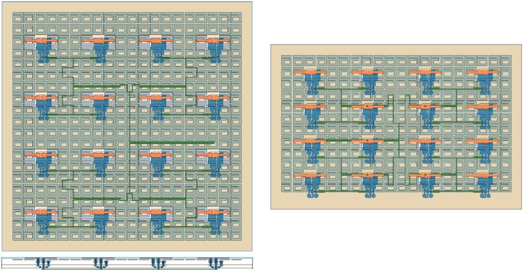
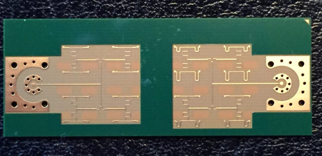
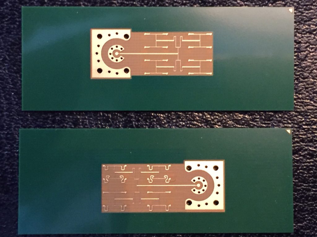
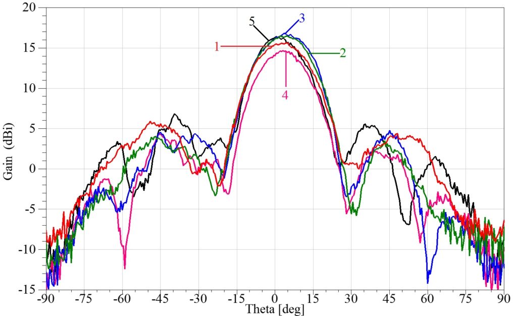
Fig. 6 presents the measured array gain versus angle, on the H-plane, for all the frequencies covering the 60-GHz operation band, and for in-phase excitation. The maximum measured gain is at broadside and varies from 15 to 17 dBi (reached at 58, 60 and 64 GHz).
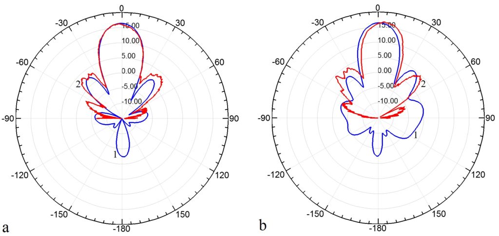
In Fig. 7 we show the measured total gain patterns versus angle for the square array with the in-phase excitation at 60 GHz and compare them to theoretical predictions for both the E-plane and H-plane cuts. The agreement between theoretical simulations and measurements is excellent. In conclusion, these spiral AMC arrays are ideal for a completely integrated 3D package-die transceiver solution for mm-wave 5G/60GHz, for their size, impedance matching bandwidth, gain and scanning performance and significantly enable its commercialization.