Electrically Small Antennas
An electrically small 3-D Folded Grounded Loop Antenna for omnidirectional connectivity
Electrically small antennas are of intense and increasing academic and industrial interest due to the advent of ubiquitous RFID devices and more generally within the Internet of Things (IoT) applications. For most of these applications antennas will have to be and as small as possible, when integrated within a transceiver, while maintaining significant efficiency values. Of particular interest are antennas that can radiate omnidirectionally along a planar surface, thus establishing optimal connectivity capabilities for devices surrounding the corresponding transmitter. Such antennas are also important for energy harvesting but also for near-field wireless charging applications. In this work we describe an electrically small antenna of size ka ≈ 0.25, where a is its effective radius and k the wave vector at operating frequency. The antenna geometry is a 3-dimensional folded meandering loop and contains its own ground, so that it becomes insensitive to the integration environment. The radiation efficiency of the antenna is 70% and it radiates as a vertically polarized dipole. The operating frequency chosen to target RFID/IoT applications at 915 MHz and the impedance matching bandwidth, as realized, is narrow but appropriate for such applications, and may be further increased if appropriate matching networks are used. In Fig. 1 we show a photograph of the fabricated prototype. The design is all laid out in stamped metal for very inexpensive mass-fabrication, and pure Cu is the metal of choice since it has maximum conductivity.

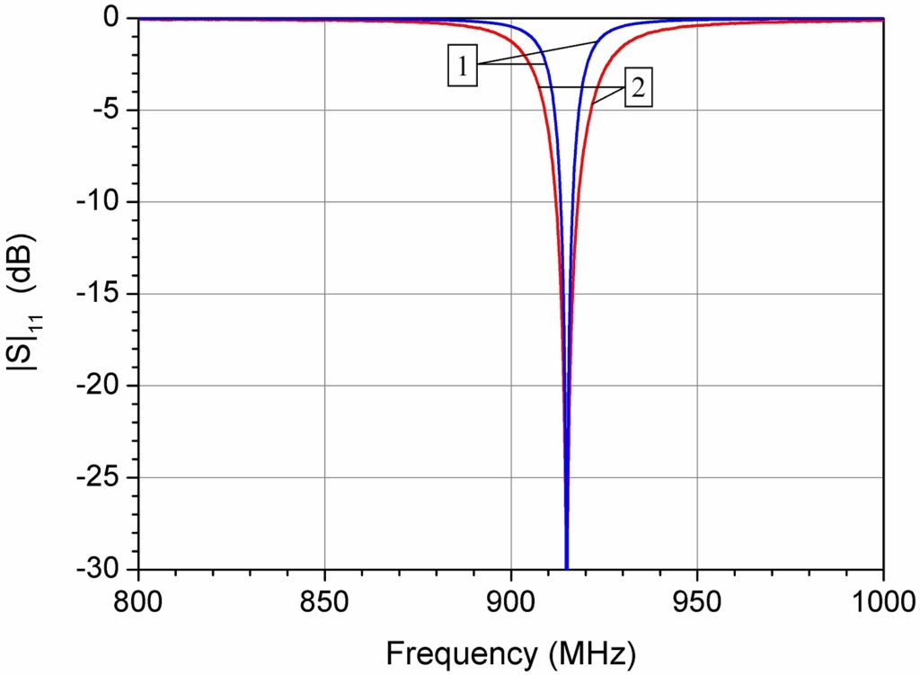
In Fig. 2 we compare the theoretical versus the measured return loss of the antenna. The -10 dB impedance matching bandwidth of the antenna is measured at about 5.7 MHz, larger than the simulated one. Fabrication inaccuracies, surface roughness as well as other distributed parasitic matching effects may cause this difference. Resonant frequencies are in excellent agreement.
In Figs. 3 a, b we compare the total gain of the antenna measured in an anechoic chamber with the corresponding simulated quantity, at 915 MHz, for the two principal cuts of the 3-dimensional radiation pattern. Fig. 3a is the cut on the [yz] plane, i.e., it is the function GTOT (θ, φ=90°), while Fig. 3b shows the corresponding comparison for the cut on the [xy] plane, hence it plots the function GTOT (θ = 90°, φ) .
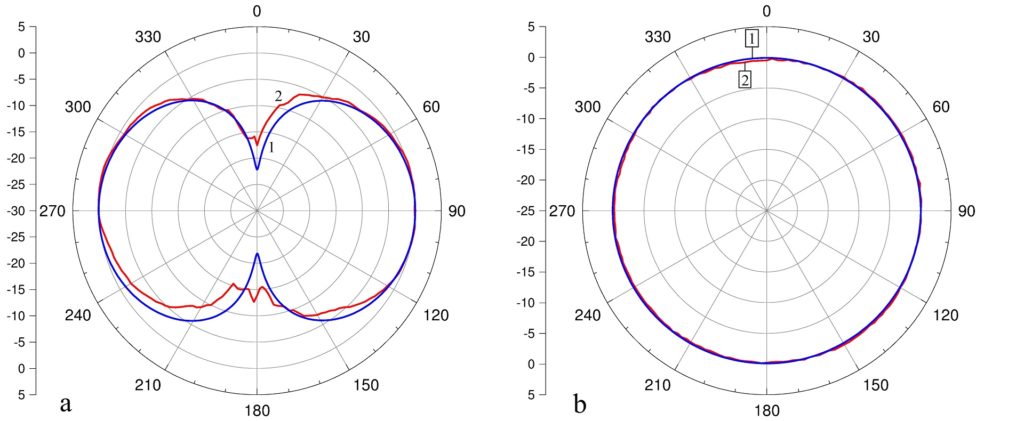
Both measurements are in excellent agreement with the corresponding theoretical simulations and show an antenna radiating omnidirectionally as a dipole perpendicular to the [xy] plane, with a 0 dBi gain. The antenna therefore acts as a dipole, completely linearly polarized with vertical polarization relative to the plane of the antenna.