Polarized Metasurfaces with applications in Antennas and Filters
A broadband polarized Artificial Magnetic Conductor Metasurface
New generations of mm-wave integrated radio transceivers offer very large bandwidths and data transmission speeds, leading to a multitude of 5g platforms and future 6g systems currently under study at even higher frequencies. Due to the high frequencies involved, antennas and arrays can for the first time be realistically integrated on the package of the transceivers, as the areas involved are commensurate with transceiver package sizes and, further, smart composite materials may also be integrated in these form factors. These possibilities are very promising for 5g and 6g networks but also for Internet of Things (IoT) applications that can be deployed in those bands [1].
Metamaterials are a class of artificially designed materials possessing important physical properties not found in natural homogeneous materials. One important class of metamaterials is Artificial Magnetic Conductors (AMC). AMC’s amplify the tangential incident electric field by 100%, rather than canceling it as electric conductors do. In this work we present a polarization-sensitive AMC material which is composed of a single surface of metallic scatterers printed on a dielectric substrate. This artificial monolayer behaves as a metasurface that has a polarization-dependent functionality: For a certain polarization of electromagnetic waves impinging on the metasurface the functionality is that of an AMC total reflector, while for the orthogonal polarization the monolayer behaves as a transparent filter. Thus, the metasurface exhibits birefringence. Polarization-dependent or anisotropic metamaterials are the subject of recent research activity for a variety of optical and microwave applications, such as polarization conversion, microwave lenses and tunable polarizers. A metasurface sample has been fabricated and characterized via Ka-band waveguide measurements validating the approach. We demonstrate the usefulness of this metasurface by an application consisting of co-located integrated antennas, exhibiting interesting properties relevant to current and future 5g/6g and IoT technologies. The metasurface is composed of long metallic strips printed in the middle of a dielectric slab, with very narrow gaps between them. The dielectric material chosen in Rogers 3203, due to its low loss and fairly standard permittivity value. The general layout of the optimized design, scaled to operate at the band [20-40]GHz, appears in Fig. 1a which shows 4 unit cells of the metasurface.
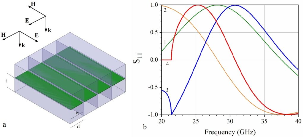
Fig. 1b shows theoretically simulated complex reflection coefficients for parallel polarization under plane-wave incidence and waveguide excitation. In both cases the metasurface acts as an AMC, reaching the perfect AMC limit of S11(f) ≈ +1 at around 30 GHz, which is the intended frequency band of operation in this work.
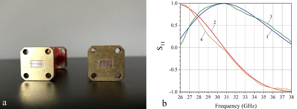
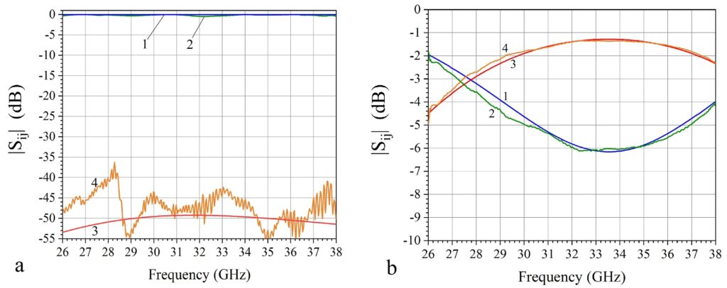
Fig. 3 (a) Parallel polarization amplitude of reflection coefficients |S11| (dB), for theoretical simulations (1) and measurements (2); Amplitude of transmission coefficients |S21| (dB), for theoretical simulations (3) and measurements (4). (b) Perpendicular polarization amplitude of reflection coefficients |S11| (dB), for theoretical simulations (1) and measurements (2); Amplitude of transmission coefficients |S21| (dB), for theoretical simulations (3) and measurements (4).
The results of Figs. 2, 3 validate the design of the metasurface and its functionality. In particular, Figs. 2b, 3a show that for parallel polarization the metasurface acts as a broadband AMC reflector reaching the perfect AMC limit at 31 GHz, while the magnitude of the reflection coefficient |S11|≈0dB, and that of the transmission coefficient |S21|≈-50dB across the band. In contrast, for perpendicular polarization, Fig. 3b shows that the metasurface functions as a mostly transparent low-loss homogeneous dielectric. We should mention that the AMC functionality of the metasurface remains the same if we omit half of the dielectric layer in Fig. 1a (the back dielectric), and still consider the reflection coefficient at the front dielectric surface. In the measurements, we preferred to use the front-back symmetric sample which shows greater transparency, despite having twice the material thickness, because it is much less reflecting under perpendicular polarization.
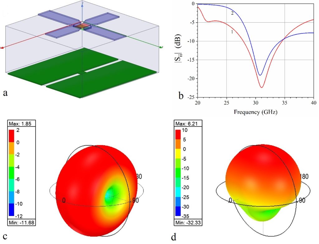
To demonstrate the usefulness of this polarized metasurface, we focus on antenna applications. We summarize a design of two dipoles perpendicularly collocated and integrated on the metasurface, and demonstrate the system’s properties through full-wave numerical simulations. The overall system is shown in Fig. 4a. Notice that we have not included the dielectric behind the metal strips, since it is not needed for the responses of Figs. 2, 3, thus reducing the overall thickness of the metasurface by half. In Fig. 4b we show the return loss of the two antennas. Both dipoles are tuned at the same frequency, designed to be the frequency of maximum AMC response of the metasurface, in Fig. 2b. In Fig. 4c we present the 3-dimensional radiation pattern of the system, when only the dipole perpendicular to the strips is firing. The figure shows the total radiation gain of the system (in dBi) at 31 GHz, with an orientation identical to that of Fig. 4a. This corresponds to the metasurface response of Fig. 3b, which is that of an essentially uniform and almost transparent dielectric slab. It is therefore not surprising that the radiation pattern is that of a standard dipole printed on a homogeneous low-loss dielectric slab, radiating omnidirectionally with maximum gain 1.85 dBi, fully linearly polarized along the dipole direction, despite the existence of the underlying metallic strips occupying most of the substrate surface, which appear invisible. Fig. 4d shows the corresponding 3-dimensional radiation gain of the system at 31 GHz, when only the dipole parallel to the strips is firing. This corresponds to the metasurface response of Figs. 2b, 3a, which is the functionality of an almost ideal AMC at that frequency. We see now that the pattern is very different from the omnidirectional pattern of Fig. 4c. The dipole becomes a directional antenna, since the metasurface acts as a perfect AMC reflector, but without shorting the dipole printed on its surface, as would happen with an ordinary electric conductor. Hence, we obtain a directive beam of 6.2 dBi gain, a gain increase of 170% relative to the perpendicular dipole, and the front-to-back ratio of the antenna gain is about 15dB. Therefore, this becomes a very directive antenna with negligible back radiation, despite the fact that the whole system in Fig. 4a, including the AMC reflector area, has a very compact lateral size of about 1/3 wavelengths.
This system is of interest, because it demonstrates that antennas can be co-located on this metasurface and, due to the metasurface’s designed birefringence, they can have complementary radiation properties which are very useful for increased channel capacity applications (such as pattern diversity) of multifunctional radiation links for both transmitters and receivers, while occupying modest areas. Such capabilities are important for novel IoT or RF harvesting systems.