Resonantly Transparent Metasurfaces
Extraordinary Electromagnetic Transmission in Almost-shorted Dual Screens
Good electric conductors are completely opaque to electromagnetic waves at any frequency up to the plasma frequency of the corresponding metal. At microwave and mm-wave frequencies, a planar screen made of metals like Cu and Al behave almost as Perfect Electric Conductors (PEC) with a complex reflection coefficient extremely close to the PEC value S11=-1, while the corresponding transmission coefficient is S21= 0 . This work advances and analyzes a metasurface presenting extraordinary resonant electromagnetic transmission properties. The system consists of an array of metal disks interacting with the dual array of holes, i.e., with a metal screen containing the negative printing of the disc array. The two arrays can be ultra-thin and arbitrarily close to each other. We show that a new phenomenon of resonant extraordinary transmission occurs, under these conditions. The transmission is extraordinary because it involves a system almost completely shorted, i.e., a composite screen that is almost completely metallized. The physical mechanism for this phenomenon is based on a single-frequency cancellation between the scattering of electromagnetic waves from the disk array and from the negatively printed (hole) array. This work presents a general analytical theoretical analysis of dual screens, treating the phenomenon of resonant transmission in a unified way focusing on ultra-thin systems, either for dual screens in the regime of extraordinary transmission described above (i.e., when the dual screens are complementary and almost shorted), or for general capacitive-reactive dual screens. Further, numerical studies using the HFSS full-wave simulator are presented, corroborating the analytical results. A special case of this approach describes the class of screens composed of coaxial hole arrays of arbitrary shape. Experimental validation of the theory and simulations is supplied by construction and measurement of a prototype waveguide filter. We present all our results for microwave/mm-wave frequencies but the same effect clearly exists at optical frequencies.
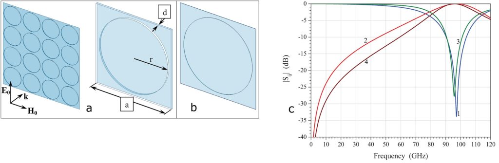
We will first test our theory focusing on complementary dual screens, Fig. 1, with zero-thickness PEC metallization, aspect ratios as noted and length scale fixed at 2r = 1mm. For theoretical validation, we will compare our analytical predictions with numerical electromagnetic simulations using the HFSS finite-element code. In Fig. 1c we compare results for d = 5µm (U.C. of Fig. 1b). There is rather excellent agreement between the analytical results, where the full high-order expressions have been used, and the simulations throughout the frequencies examined, from DC up to 120 GHz. We notice indeed that we have extraordinary power transmission reaching almost 100% at 90-100 GHz.
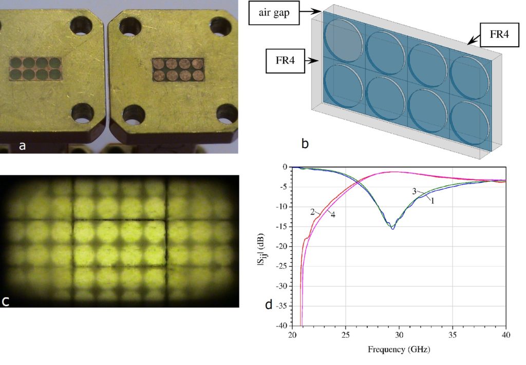
We validated the theory experimentally by constructing and measuring a prototype complementary dual screen following the layout of Fig. 1. We measured its response by inserting it into a rectangular waveguide, and designing the U.C. so that the system has extraordinary resonant transmission in the TE10 frequency band of the waveguide. The screen is composed of two thin FR4 layers, of complex permittivity ε = 4.4(1-j0.02), each with a single metallization on the surface. One layer contains 2×4 U.C. of discs, while the other the negative printing. The FR4 layers have been milled to a thickness of 600µm each, while the Cu metallization is 17 microns thick. The dual screen is designed to fit a Ka-band rectangular waveguide with inner dimensions 3.6mm×7.2mm. Hence the U.C. size is a = 1.8 mm. We choose the ratio a /2r = 1.1, the same as in Fig. 1, giving a disk/hole radius r = 0.82 mm.
The two FR4 layers are then inserted inside one end of a rectangular waveguide section, with the metallization facing outwards, as shown in the photograph of Fig. 2a. Using an appropriate spacer, the two metallizations are separated by an air gap d = 80 µm, when the two waveguide pieces are brought together, reconstructing the schematic of the fabricated complementary dual screen as shown in Fig. 2b.The correspondence of the waveguide excitation to oblique plane-wave incidence on a laterally infinite screen is due to the scatterer images on the waveguide walls. This is shown in Fig. 2c, where a photograph of the hole FR4 of Fig. 2a has been taken from the opposite (open) end of the waveguide section. Fig. 2d shows a comparison between theoretical HFSS simulations and measurements. The waveguide cut-off frequency is 21 GHz, while the upper frequency limit of the VNA coincides with the cut-off of higher guided modes. In the range shown, only the dominant mode propagates. The agreement between theory and measurement is excellent. The extraordinary resonant transmission peaks at 29 GHz, and equals -1 dB (80%) while the dielectric, metallization and waveguide loss is about 17%.