Sensor Control & RF Passive Sensor Tags
Re-configurable embedded system for capacitive sensor array readout
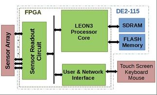
In this collaborative work with the University of West Attika, a smart flexible embedded system for measuring capacitance sensors is developed. The system comprises of a sensor interface circuit and an Aeroflex Gaisler LEON3 processor equipped with the necessary peripherals in order to support an embedded LINUX operating system. The system has been implemented and tested using the Terasic’s DE2-115 development board, which hosts an ALTERA CYCLON IV FPGA device, and a custom board hosting the sensor elements. The sensor readout circuit converts the capacitance variations into frequency changes by using a specially designed ring oscillator implemented on the FPGA, which provides flexibility to the measurement time, the accuracy and the range of elaborated frequencies. In addition, the capability to support the Advanced Microcontroller Bus Architecture (AMBA) Periphery Bus (APB) has been implemented so that it operates as a typical peripheral of the LEON3 core, thus allowing the user to efficiently manage it through the application software.
Temperature control for uPCR devices.
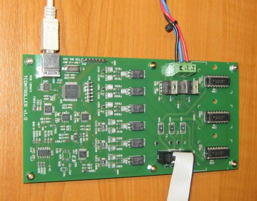
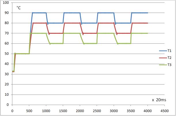
A temperature controller system for the control of the temperature of up to three heating zones of Lab-on-Chip devices for isothermal and PCR DNA amplification has been developed. The LoC consists of a microfluidic network and three embedded resistive heating elements (microheaters) fabricated on a common PCB substrate. The layout of the 3 heating elements forms 3 planar temperature zones and the controller is designed to keep the temperature variation within each zone within 1 deg. C.
The circuit is built around a micro-controller (for the PID control loop and communication) and 16-bit external DACs and ADCs for driving and sensing the micro-heaters. Temperature control is achieved by controlling the voltage across the resistive heaters whilst a small sensing resistor is used to measure the current flowing through them. Communication with a host PC uses a USB serial port in order to set the operating parameters of the PCR (e.g. zone temperatures, calibration data and control coefficients) as well as log data during its operation.
RF harvesting and passive sensor tags
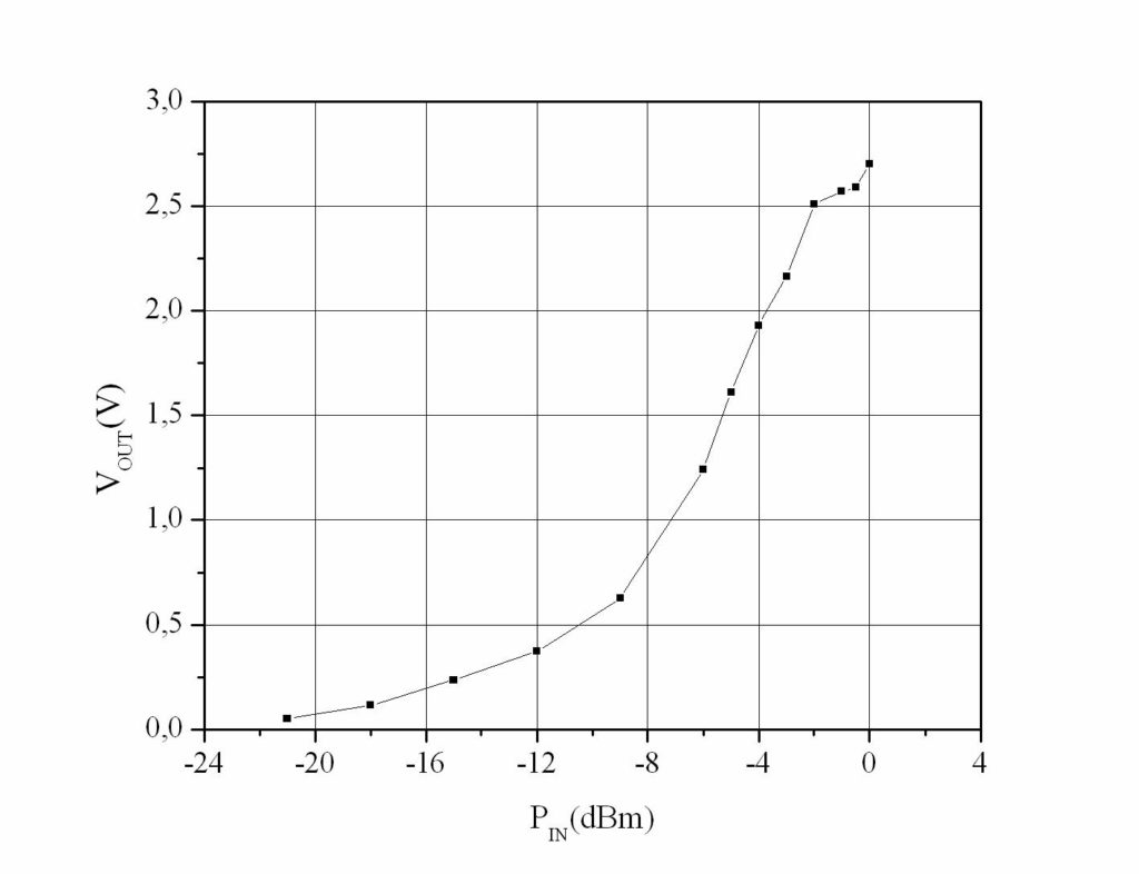
RF power-harvesting systems are of particular interest in autonomous sensor tag design because of their ability to draw power from electromagnetic fields generated by controlled and stable RF power sources. RF sensor tags are based on the technology of RF identification systems which are widely used in product chain applications. A variety of real-time monitoring applications such as structural health monitoring in large structures, often require the deployment of such remotely powered sensor tags. In this case the tags are often installed in inaccessible places or integrated in the monitored structure during construction.
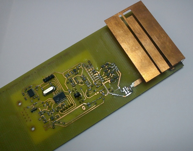
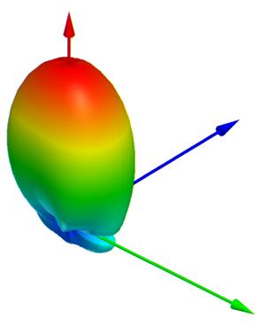
A power-harvester with an embedded antenna operating at the 430 MHz band capable of operating near ground or metal planes has been developed in close co-operation with the Electromagnetic Metamaterials and Novel RF Systems group. The tag uses discrete components including an onboard microcontroller for supervision of system functions and interfacing with different types of low power sensors, thus resulting to a flexible passive sensor platform. The system comprises a low-profile optimized multi-slotted PIFA (Planar Inverted F Antenna) integrated within the system volume, which enables operation near metal and ground surfaces, and results in a slim packaged system.
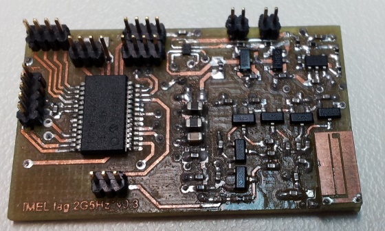
A smaller size harvester operating at 2.5GHz using a low profile and small footprint PIFA has also been developed. Integrated on the systems’ PCB it provides an inexpensive approach of equal or better performance to expensive ceramic antennas. The small size is due to the optimized multiple slots and the scaling with the permittivity of the FR4.